- RS Home
- >
- Feature Articles
- >
- All Articles
- >
-
Avoiding Failure, Tolerating Faults
Part 1: Approaches to Reliable Design: Fault avoidance
Following the launch or announcement of ‘safety’ microcontrollers from Texas Instruments, Freescale and Infineon, we present the first part in a series covering the theory and practical techniques behind reliability and redundancy in safety-critical systems.
In the last quarter of the 20th century, the word ‘computer’ became synonymous with unreliability. Whenever a system failed it was always the computer that had made the mistake. This was often unjustified and became a convenient mechanism for covering up human errors perpetrated either by the programmer or the operator. The computer became a scapegoat for our own failings and everybody was happy to put up with this situation as long as so-called ‘computer errors’ didn’t lead to injuries or death. But technology moved on, and computers became mobile in cars and then airborne, controlling non-safety-critical functions such as windscreen wipers and navigation. All that changed when flight control systems became computerised: first with military aircraft and then with civilian types such as the Airbus A320. Nowadays even cars are packed with microcontrollers and they too are taking over safetycritical functions like emergency braking and airbag operation. Recently, Google has demonstrated that truly driverless cars are a practical proposition. Where does all this leave the public’s attitude towards computer errors now? Fortunately aircraft and car manufacturers realised early on that shrugging off a plane crash or highway pile-up involving hundreds of deaths as ‘just a computer error’ was not going to be acceptable. Much research into making computers ‘infallible’ has taken place over the last fifty years following two lines of attack: firstly fault avoidance and then with increasing machine intelligence, fault tolerance.
As a concept, computer reliability can have as many loose definitions as there are computer operators and users. It also depends on the level of viewpoint; a computer installation manager may see his system as reliable because, generally, throughput matches requirements. The operator may have a less than charitable view if, in order to achieve this throughput, he has to correct mistakes and call for the maintenance engineer to replace components frequently. The maintenance engineer may regard the system as totally unreliable because he carries out preventative work as well as locating potential faults and eliminating others which that, as yet, have not caused errors ‘downstream’. This traditional human approach to reliability is just not good enough in for safety-critical systems such as flight control.
Reliability Definitions
- Reliability is the probability that a given system will perform a required function under stated conditions for a stated period of time.
- A fault is the direct cause of the system not performing its designated task correctly. A fault can exist in hardware, timing or in the software (bugs). It can also be permanent (hard) or transient in nature.
- A failure is the deviation from the system specification due to the existence of a fault. This in effect means that the processor gets itself into an incorrect state after sequencing through a number of correct states.
- An error is the manifestation of the machine failure in the form of a mistake in a particular piece of program calculation.
When designing the system, likely causes of faults must be considered and these are termed “threats”
- A threat is a stress producing a fault and can be normal environmental, abnormal environmental, or design error.
In order to arrive at a mathematical function for reliability, two main assumptions are made. These are that device failures are random in occurrence and are thus statistically independent, and the failure rate, expressed as so many failures per hour, is a constant over the equipment lifetime. Both these assumptions are shaky but providing certain conditions are met, they have been found to be reasonably valid for system analysis purposes. Statistical independence assumes that the failure of one component does not impose increased stress on its neighbour thus increasing their likely failure rate.
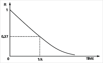
When computers were constructed from discrete transistors, resistors, etc, then failure short circuit failure of a capacitor, say, could cause overload of a transistor and lead to cascaded failures. Integrated circuit logic elements are less susceptible to cascading damage and should conform more closely to the reliability model. The constant failure rate requirement can be met if the initial “burn-in” and “wear-out” phases of system life are left out (Figure. 1) and only the flat part of the “bath-tub” curve is used. The burn-in phase should eliminate all the inherently faulty components, hardware design errors and program ‘bugs’. Hence the theoretical reliability of a non-redundant system module with respect to time is given by:-
R(t) = e-lt where l is a constant failure rate.

Figure 1. Component failure rate with time
This yields the exponential curve shown in Figure. 2. The module is in theory totally reliable, R(t) = 1 when time = 0 which is when the system enters the constant failure rate area of its lifetime (Figure. 1).

Figure 2. Reliability of a simplex unit
Fault Avoidance

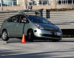
Google has demonstrated that truly driverless cars are a practical proposition.
Traditional fault avoidance or fault intolerance aims to increase the MTBF of the system by improving the individual module and component MTBFs. This is done to the point where the required lifetime or mission time of the equipment is considerably less than the system MTBF, yielding probabilities of successful operation of say 90-99%. Generally the mission time is used as the basis for calculation particularly in the military aircraft field, where the MTBF may only be hours. Fault avoidance is achieved in several ways:-
- Component quality control. Nowadays this means increased vigilance for counterfeit parts.
- Heavy component de-rating; only using, say, 10% of power capabilities.
- Use of automotive or military temperature range versions of parts.
- Reduced environmental stress using cooling systems, etc.
- Absolute minimum of components used to do the job, i.e. design efficiency with no redundancy.
These techniques have been used extensively in military applications because of the requirement to keep weight down – at any cost. The need for longterm reliability has usually been of secondary concern as mission times in this area are often measured in hours, sometimes even minutes or seconds for a weapon system such as a guided missile. For the military, the need for low deterioration during longterm power-off storage is more important. Safety is also less of an issue than in the civilian sector.
Civilian aerospace and automotive projects may have similarly short mission times, but the costs of designing for fault avoidance may be prohibitive. Fortunately, large-scale integrated circuits offer the prospect of fault-tolerance at low cost: self-checking systems, onboard ‘spares’ and automatic recovery. In non-military applications, fault tolerance will make developments such as driverless vehicles not only possible, but also safe.
In part 2 we will look at the theoretical and practical implications of fault-tolerant design including examples from aviation in the Airbus, and space exploration with the Space Shuttle and robotic planetary explorers.
Fault avoidance was discussed in Part 1: in this issue we describe hardware design techniques for coping with transient and hard faults in microcontroller-based systems once they do occur.
Fault tolerance assumes that faults are likely to occur no matter how many steps are taken to avoid them.
- A Fail-Safe system cannot resume safe operation after fault detection, but it will shut down in a predictable manner without producing erroneous outputs.
- A Fault-Tolerant system has the built-in capability (without external assistance) to preserve the continued correct execution of its programs and input/output functions in the presence of a certain set of operational faults.
This deceptively simple definition is in fact very difficult to translate into a real system. Assuming that we have a permanent or transient fault in the system then three requirements must be met to satisfy the desire for ‘continued correct execution’. These are:-
-
Error Detection.
The system must be able to detect its own mistakes. - Fault Diagnosis.
Having detected an error while running the application program, the system must be able to isolate the fault to a group of components or modules which can be bypassed, replaced under processor control or shut down. - Fault Recovery.
Once the fault has been located, the system must take action to eliminate or minimise its effect. For a transient fault, a simple ‘re-try’ may be enough
Ideally, the above three processes take place as quickly as possible, so that interruption to data throughput is kept minor. Protective redundancy is introduced in the form of extra hardware or software or both, in an attempt to achieve the design goal of almost instant recovery after failure. In practical terms it is almost impossible to cater for every single type of component failure likely to occur. Some faults are bound to cause catastrophic system loss, and all that can be done is to reduce their probability of occurrence to an acceptably low figure. Non-redundant circuits such as clock generators need special design attention to reduce the probability of a single fault bringing down an otherwise fault tolerant system.
Coverage is the conditional probability that a fault will be detected and dealt with safely. The term ‘Safely’ can mean either a system shutdown with no bad effects (Fail-Safe) or isolation of the faulty component with continued operation (Fault Tolerance in a redundancy-based system). This term is also called the Safe Failure Fraction (SFF) and is expressed as a percentage. Of course there are situations where even a controlled loss of function is not acceptable: consider what would happen if the automatic controls in a driverless car just shut down in the middle of a high-speed manoeuvre. In this scenario fault-tolerance is the only option.
The concept of coverage allows the effectiveness of particular reliability schemes to be assessed in terms of their ability to detect and deal with all the possible failure modes. Coverage must be almost total if predicted reliability is to be achieved. Fault tolerance and fault avoidance are not mutually exclusive and both techniques can be combined when working up a particular design. The introduction of redundant components and the inclusion of spare modules does not automatically improve system reliability. Indeed, replication of basically low quality components will make the redundant system less likely to complete its mission than the simplex one. The use of top-quality components and de-rated design are necessary for the maximum benefit of fault-tolerant computing to be achieved. This means that the system will have increased availability and the probability of mission success is enhanced even with the presence of failed components. Special attention to availability issues at the design stage have enabled the Mars Exploration Rovers launched in 2003 to exceed their expected mission lifetime by many years.
Simplex and Simplex + Diagnostics
Simplex or 1oo1 (One out of One) systems have no means of detecting faults and have a high probability of failing unsafe. In simplex + diagnostics or 1oo1D, checking circuits are incorporated to monitor the processor operation without any ‘overheads’ in a speed critical real-time system.
A ‘Watch Dog’ timer, sometimes included on the processor chip or as part of a separate supervisor device, is widely used to detect processor failure. It usually forces a system reset when a program-generated signal disappears. These very simple devices often incorporate power supply monitoring as well. To meet the needs of the new safety standards, ISO26262 & IEC61508 a much more comprehensive solution is required. The Yogitech fRCPU for an ARM® Cortex M3 based MCU [1] is one example, the Infineon CIC61508 Signature Window Watchdog [2] for their TriCore™ processor another. These Diagnostic devices turn a Simplex or 1oo1 system into a 1oo1D type which can be used to realize a IEC61508 SIL3 certified system. This means it has an SFF > 99% and the output will be Fail-Safe.
The Texas Instruments TMS470M ‘safety’ microcontroller, part of their Hercules™ range, features a single Cortex-M3 core with errorcorrecting and self-test logic all on one chip [3]. However it cannot meet the IEC61508 safety criteria as its SFF is less than 60%. This is because the error checking logic cannot detect more than 60% of possible transient or systematic errors made by the core. A way to boost the coverage is the time-honoured technique of two or more cores running the same program and comparing outputs.
Multi-Processor Modular Redundancy
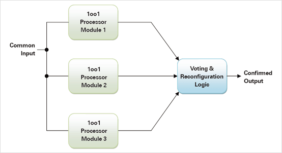
Traditionally, redundancy in computer control systems has referred to the duplication (DMR or 2oo2), triplication (TMR or 2oo3) or even quadruplexing (QMR or 2oo4) of the processor units with the same program running on each in ‘lock-step’. Separate comparison or voting logic only allows an output through to an actuator if a majority of processors agree. This means DMR is not fault tolerant because the voting logic cannot tell which output is incorrect, so both processors must be shut down in a Fail-Safe manner. However DMR with an SFF > 99% could still meet the SIL3 criteria. TMR allows one processor to fail with continued operation as long as the remaining two agree. (Figure.1) A QMR system should be able to handle two failures with no reduction in performance. TMR and QMR based systems should meet the criteria for SIL4 if they can achieve an SFF > 99% because they are also fault tolerant.

Figure 1. A single-fault tolerant system based
on Triple Modular Redundancy
The Texas Instruments Hercules Cortex-R4F based TMS570LS and RM48x microcontrollers contain two processor cores which execute the same program in lock-step, but one serves only as a slave checking device producing outputs for comparison with the Master [3]. Only the Master outputs are available to the rest of the system so a DMR 1oo2 system cannot be constructed with one device. Instead, we have a 1oo1D arrangement that can meet the SFF > 99% criteria for IEC61508 SIL3.
Transient & Hard Faults
If a checking system comes up with an error, it may just be a one-off caused by the impact of a stray cosmic particle flipping the state of a RAM cell for example. The effect of this transient fault may be eliminated by a simple re-try of the program segment that led to the error. The ability to perform a re-try must be built into the system otherwise hardware resources will be shut down unnecessarily. Time and effort spent getting these circuits/software right will pay handsome dividends if the system works in an electrically noisy environment. Of course the error checking system must also be able to sense a ‘hard’ fault quickly and avoid pointless re-tries.
Static & Dynamic Redundancy
Basic modular redundancy with voting circuits is normally classified as Static, where all modules are ‘hot’ and running. A processor module may be ignored or powered-down when it develops a hard fault.
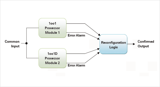
Dynamic redundancy involves hot or cold standby spare units which are switched in and out as required by fault detection logic and/or software. Dynamic redundancy has been used extensively on the Space Shuttle [4] and Airbus aircraft [5]. In the latter example, a further precaution was taken against common-mode faults by introducing Diversity whereby processor modules are based on different microcontroller platforms with software written by independent teams. These systems feature dual processor 1oo1D modules which could now be replaced with single chips such as the Hercules dual-core devices. For example two chips could be combined to form a fault tolerant 1oo2D system compliant with SIL4. (Figure. 2) In this case both processors are ‘hot’ and both receive the same inputs including a common Reset. When a switch is commanded, the outputs of the standby unit replace those of the failed module. Although processor clocks are not synchronised, there should be no more than a minor glitch at switchover.

Figure 2. A single-fault tolerant system based
on two dual-core safety microcontrollers.
Conclusion
Until recently, the concept of fault tolerance has been linked mainly to very high cost projects involving air- and space-craft because of the huge development costs. It is likely that automotive systems will require the use of these techniques as driver-less vehicles become a reality on public roads. Automotive and industrial applications must comply with the international standards for reliability ISO26262 and IEC61508 respectively and fortunately the new generation of ‘Safety’ microcontrollers will enable engineers to produce designs compliant with these standards.
| [1] | www.fr.yogitech.com |
| [2] | www.infineon.com |
| [3] | www.ti.com |
| [4] | Paper: Redundancy Management Technique for Space Shuttle Computers, J.R.Sklaroff, IBM Journal Research & Development, 1976 |
| [5] | Paper: AIRBUS A320/A330/A340 Electrical Flight Controls, A Family of Fault-Tolerant Systems, Dominique Britxe, Pascal Traverse, IEEE 1993 |
Back to top