LCR Meters
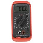
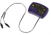
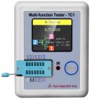
LCR meters are electronic test instruments that measure the inductance (L), capacitance (C), and resistance (R) of electronic components.
Inductance occurs when a change in current flowing through a conductor induces a corresponding voltage change in the conductor and surrounding conductors. Capacitance is the ability of a body or conductor to store electrical charge. Resistance is the opposition a conductor offers to the passage of electric current.
Most LCR meters use AC signals to measure the impedance of components. When using an LCR meter, make sure you are using the correct settings as the wrong settings can cause poor measurement accuracy. Digital LCR meters are generally more accurate than analogue models. A digital LCR meter measures the voltage (V), current (I), and phase angle between current and voltage across a Device Under Test (DUT) to determine impedance parameters.
What Are the Uses of an LCR Meter?
LCR meters are primarily deployed for the detailed characterisation of passive electronic components. Their fundamental operation involves subjecting a Device Under Test (DUT) to a controlled AC signal at a specific frequency and measuring its electrical response to determine various impedance parameters.
Core Functions and Technical Definitions
- Inductance (L): Measured in Henries (H), quantifies a component's capacity to store energy in a magnetic field.
- Capacitance (C): Measured in Farads (F), defines a component's ability to store energy in an electric field.
- Resistance (R): Measured in Ohms (Ω), represents the opposition to current flow (both AC and DC).
- Impedance (Z): The total frequency-dependent opposition to AC flow, a complex value including resistance and reactance.
- Dissipation Factor (D): A measure of energy loss in a component, lower values are generally preferred. For capacitors, D=ESR/∣XC∣.
- Quality Factor (Q): The reciprocal of D (Q=1/D), indicating component efficiency; a higher Q signifies lower loss.
- Equivalent Series Resistance (ESR): The effective internal resistance of a component at a given frequency, crucial for capacitor and inductor performance.
What Are the Types of LCR Meters?
LCR meters are principally differentiated by their form factor and performance capabilities, mainly falling into handheld or benchtop categories.
Handheld LCR Meters
Handheld LCR meters offer portability and battery operation, suiting field service, on-site troubleshooting, and rapid component checks. They have multiple test frequencies, and the data captured can be transferred to a PC via a USB port. While convenient, they generally have more constrained measurement accuracy, frequency options, and fewer advanced features than benchtop models.
Benchtop LCR Meters
Benchtop LCR meters are designed for laboratory, R&D, and production testing. They typically provide superior accuracy, broader test frequency ranges (Hz to MHz/GHz), comprehensive measurement parameters, and connectivity options (GPIB, USB, LAN) for automation and data logging. They facilitate stable, repeatable measurements through enhanced shielding and power regulation.
Techniques Used with LCR Meters
Accurate LCR measurements necessitate specific techniques to mitigate errors and obtain pertinent data, addressing signal levels, connections, and parasitic effects.
Test Signal Level and Connection Methods
The AC stimulus level (voltage or current) can be adjusted to match component specifications or application conditions. Connection integrity is vital:
- Two-Terminal (2T): Simple, but prone to lead impedance errors.
- Four-Terminal (4T) Kelvin: Minimises lead resistance errors, essential for low-impedance DUTs.
- Five-Terminal (5T): Includes a guard terminal to reduce stray capacitance effects, crucial for high-impedance measurements.
Open/Short/Load Compensation
These procedures nullify test fixture and lead parasitics:
- Open Compensation: Corrects for fixture stray capacitance.
- Short Compensation: Negates fixture residual inductance and resistance.
- Load Compensation: Uses a precision standard for overall system calibration, enhancing accuracy.
Equivalent Circuit Modes
Users can select series (Rs-Ls/Cs) or parallel (Rp||Lp/Cp) equivalent circuit models. The series model is generally for low-impedance DUTs, while the parallel model suits high-impedance DUTs.
Key Features to Look for in an LCR Meter
Selection of an LCR tester should be guided by critical performance specifications and functional features relevant to the intended applications.
Measurement Range and Accuracy
Ensure the meter's L, C, and R measurement ranges cover the component values to be tested. Accuracy, specified as a percentage of reading plus a fixed error, is paramount for reliable component validation. It varies with parameter, range, and frequency.
Test Frequencies
The availability of appropriate test frequencies is crucial, as component impedance is frequency-dependent. Basic meters offer fixed frequencies (e.g., 100 Hz, 1 kHz, 100 kHz), while advanced units provide wide, selectable ranges (up to MHz/GHz) to simulate operational conditions. Electrical components need to be tested at the frequency for which the final product/application will be utilised.
Display Type and Readability
A clear display showing primary and secondary parameters (e.g., L, C, R, Z, D, Q, ESR) simultaneously is essential. LCD or TFT screens with backlighting enhance readability.
Auto-Ranging Capabilities
Auto-ranging simplifies operation by automatically selecting the optimal measurement range. Manual ranging provides control for specific tests. Most professional meters offer both.
Differences Between Handheld and Benchtop LCR Meters
Choosing between handheld and benchtop LCR meters involves a trade-off between portability and performance characteristics.
Portability vs. Advanced Functionality
Handheld meters excel in portability for field use but offer less advanced functionality. Benchtop meters provide superior features, wider parameter measurement, and automation capabilities, but are designed for stationary lab/production use.
Accuracy and Frequency Range
Bench LCR meters generally deliver higher accuracy and broader frequency ranges due to more sophisticated circuitry and stable AC power. Handhelds have more limited specifications in these areas.
Ease of Use in Field vs. Lab Environments
Handheld units are designed for quick field measurements with simpler interfaces. Benchtop instruments, suited for lab environments, offer more complex setups for precise, configurable testing, often with specialised test fixtures.
Power Options
Handheld LCR meters are typically battery-powered, enhancing field utility. Benchtop LCR meters are AC-powered, supporting their higher performance and continuous operation.
Industrial Applications of LCR Meters in Different Industries
LCR meters are critical for component verification and system integrity across diverse industrial sectors.
Electronics Manufacturing
LCR meters are used for incoming Quality Control (QC) of passive components (resistors, capacitors, inductors) and for verifying PCB assembly integrity. They are essential for ensuring components meet specified tolerances.
Automotive
Employed for testing sensor coils (e.g., ABS, engine sensors), capacitors in ECUs, and wiring harness characteristics, which is crucial for the reliability of automotive electronics.
Aerospace
LCR meters are vital for verifying high-precision component performance in avionics, communication, and control systems where reliability is paramount. They are also used for component characterisation under specific operational conditions.
Telecommunications
Applied to test components impacting signal integrity, such as inductors, capacitors, and filters in RF circuits and high-speed data systems. Measurement of ESR and Q factor at operational frequencies is key.
The Leading Supplier and Distributor of LCR Meters in Malaysia
RS is your trusted source for high-precision LCR meters in Malaysia. We offer a comprehensive selection from leading brands such as BK Precision, Keysight Technologies, and RS PRO, catering to various testing needs and measurement ranges. Whether you're looking for handheld models for field diagnostics or benchtop units for laboratory-grade accuracy, our inventory supports a wide range of industrial applications.
In addition to LCR meters, we stock complementary electronic test tools and accessories, such as banana plugs, BNC connectors, and ESD testers to help streamline your workflow. Explore our range of digital and analogue LCR meters online and complete your purchase with ease. For more information on delivery options, lead times, and shipping fees, please visit our delivery page.
Related links
- BK Precision BK895 Bench LCR Meter 100mF 100000H
- BK Precision BK880 Handheld LCR Meter 20mF 1000H
- Amprobe LCR55A Handheld LCR Meter 2mF 200H
- Keysight Technologies U1733C Handheld LCR Meter 20mF 2000H
- Peak Electronic Design ESR70 Handheld LCR Meter 22mF, 4 MΩ
- E4980BL/E4980BL-052 Bench LCR Meter
- BK Precision BK894 Bench LCR Meter 100mF 100000H
- BK Precision LCR Meter Test Lead for Use with 879B Models 878B


